The newly designed Tube Forming Module in 6.2 was released in May 2022. In this article, we’ll walk through the process of preparing a model for tube bending.
Getting Started With Tipping and Morphing
The first step is importing the geometry into Dynaform. Afterward, the tube needs modification, such as tipping and morphing.
Tipping
Tipping is used to adjust the coordinate system during product processing.
There are two types of tipping systems users can define: “Manual” and “Assign.” With manual, the user specifies the origin of coordinates, and the program automatically creates the coordinate system. With assign, the user selects the coordinate system from a list as the current coordinate system. The tipping center can also be defined by entering X, Y, and Z origin coordinates or by picking the center of the tube’s start, end, or gravity.
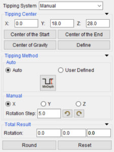
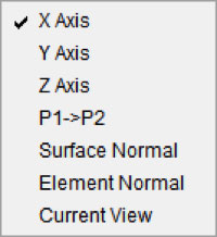
There are also two types of tipping methods, “Auto” and “Manual.” The Auto tipping method automatically adjusts the direction according to the rules according to the minimum depth. The direction for the minimum depth is set by the W direction configured in the local coordinate system during product processing. In rare instances where Auto tipping doesn’t solve the problem, you can use the Manual method and set the tipping yourself.
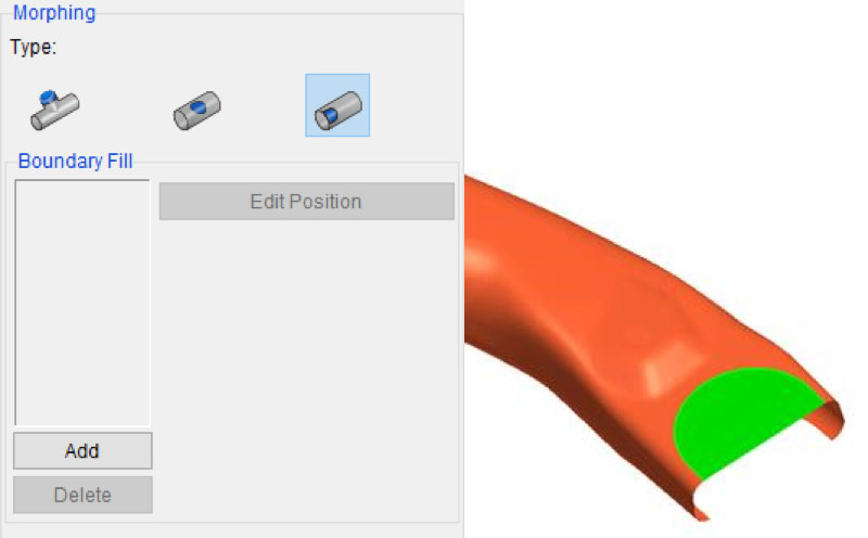
Morphing
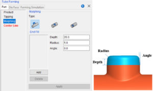
Morphing is used to preprocess the tube geometry, including the End Fill, Inner Fill, and Boundary Fill. End Fill is used to fill the end of the product and has filling parameters such as depth, radius, and angle.
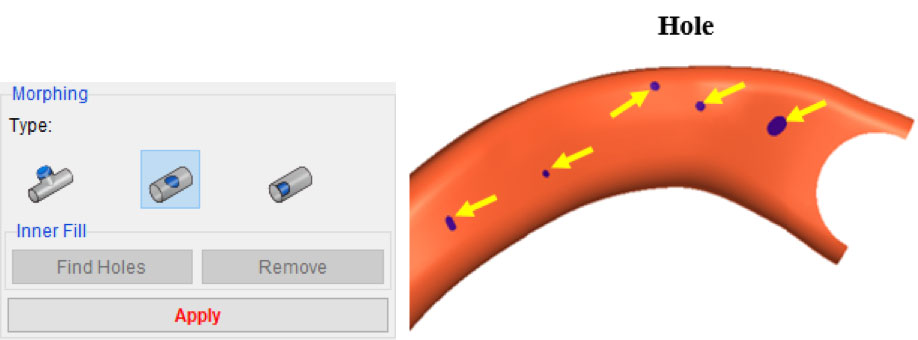
Inner Fill is used to fill an inner hole on the product. The user may fill all holes at once or select a specific hole to fill. Use the [SHIFT] key to deselect a hole. Click the Apply button to fill the selected hole(s).
Finally, Boundary Fill is used to fill the end boundary of the tube.
Center Line
After tipping and morphing, the Center Line function can be used to calculate the product’s center line and section line. circumference, and strain of section. Once calculated, you can move the position of the section by clicking and dragging. You can also view the current section, circumference, and strain by clicking on a tube section.
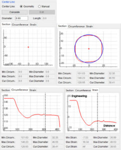
Calculating a center line allows you to quickly generate a bending line and bending table in Dynaform 6.2. The bending line is obtained by fitting the center line, and the bending table is based on the bending line.
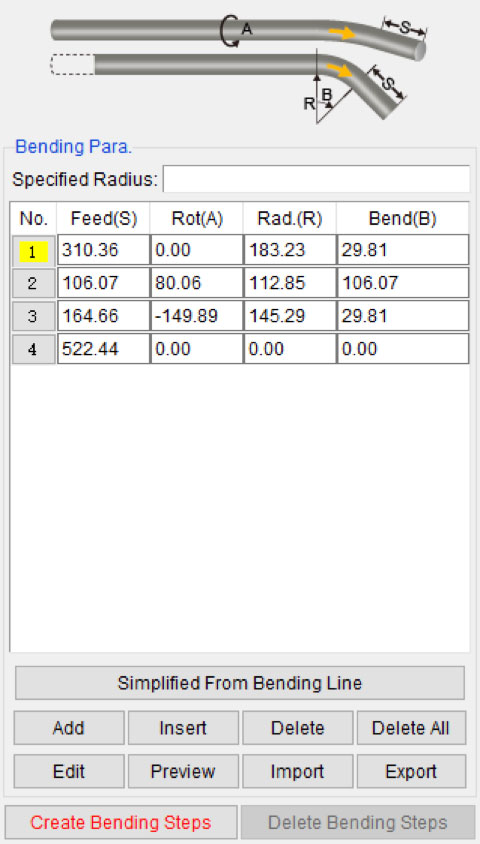
Simply click the “Simplified From Bending Line” button, and Dynaform will automatically generate the bending table from the bending line. The parameters are as follows:
- Feed (S): The distance for tube feeding.
- Rot (A): The rotation angle for the direction of tube feeding.
- Rad. (R): The radius for tube bending. If the user specifies the bending radius, the program generates a bending table according to the specified radius.
- Bend (B): The angle for tube bending.
- The user can also edit the bending table manually.
- Add: Add one row, namely, one bending step. Enter the corresponding value for Feed (S), Rot (A), Rad. (R) and end (B).
- Insert: Insert one row behind the current row.
- Delete: Delete the currently selected row.
- Delete All: Delete all data in the bending table.
- Edit: Edit the bending line and then exit the Curve Edit dialog, and the program automatically updates the bending table.
- Preview: Preview the bending process of the tube.
- Import: Import the files in the bending table into the current setting.
- Export: Export the bending table for the current setting into the file.
Reliable simulation results depend on the proper preparation of models. With the bending table, Dynaform 6.2 can create all the stages and tools for tube bending simulation. This preparation will make your work easier and more efficient.